
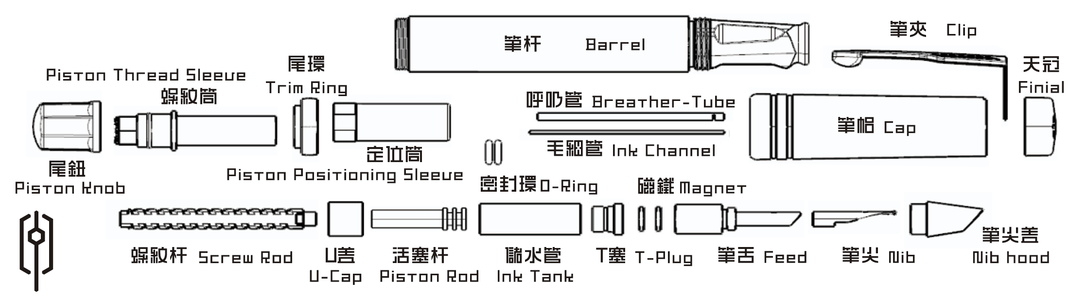
BubPens
Engineering pillar page
How the BubPens filling mechanism works.
This page explains the filling mechanism as a five-state system story. The goal is to preserve mechanical clarity in HTML while leaving a clean slot for future chapter-based motion assets.
Mechanism sequence
The core story is a five-step transfer from mechanical input to controlled ink delivery.
The sequence below is the HTML stand-in for future motion. Each step keeps the explanation, part names, and reading cues in plain text so the page remains useful even before interactive media is added.
Reset phase
How does the mechanism prepare before ink is drawn?
The filling sequence begins with internal parts aligned around the piston path. The knob, screw rod, and positioning sleeves establish a repeatable starting state so the next movement produces a controlled draw instead of a vague internal shift.
Draw phase
How does user input become a filling action?
Turning or driving the external control moves the piston-linked assembly and changes the usable volume of the chamber. That relationship is what initiates the draw toward the ink tank.
Transfer phase
How is ink guided instead of simply rushed inward?
The mechanism depends on guided transfer through narrow interfaces rather than uncontrolled flood. The breather tube, channel, and feed-side path help define where the ink moves and how pressure change is translated into direction.
Stability phase
How is the filled system sealed and controlled after transfer?
A good mechanism does not stop at getting ink inside. It also has to close, retain, and stabilize the result. Sealing elements such as the O-ring and plug-related interfaces keep the chamber behavior predictable after the draw phase has finished.
Writing phase
How does the internal system hand off to the nib?
The final state is not about the tank alone. The system becomes meaningful only when the feed and nib zone can receive ink in a stable, controlled way. That handoff turns a hidden mechanism into writing performance.
Component index
FAQ
- Is the filling mechanism only about capacity? No. Capacity matters, but retention, pressure stability, and delivery consistency are equally important.
- Why explain the mechanism as states instead of parts? Because users experience the mechanism through transitions such as filling, settling, and writing.
- What should follow this page next? BubPens Anatomy is the cleanest next step for terminology, and the Care and Cleaning Guide turns the mechanism story into ownership routine.
